How to Know the IP address of a Person on FACEBOOK
This technique works when you are chatting with that person. The first demand of operation is to close all of the website and Messengers that you are using, even clean History and delete Cookies as precaution.
Now start chatting with that person.
The first thing you do is to open start->run->cmd.exe now in it type following command:
netstat –an
and wait and watch the foreign address will be the IP address
.: How to configure Internet Connection Sharing in Windows XP :.
How to use Internet Connection Sharing
To use Internet Connection Sharing to share your Internet connection, the host computer must have one network adapter that is configured to connect to the internal network, and one network adapter or modem that is configured to connect to the Internet.
On the host computer
On the host computer, follow these steps to share the Internet connection:
Log on to the host computer as Administrator or as Owner.
Click Start, and then click Control Panel.
Click Network and Internet Connections.
Click Network Connections.
Right-click the connection that you use to connect to the Internet. For example, if you connect to the Internet by using a modem, right-click the connection that you want under Dial-up.
Click Properties.
Click the Advanced tab.
Under Internet Connection Sharing, select the Allow other network users to connect through this computer's Internet connection check box.
If you are sharing a dial-up Internet connection, select the Establish a dial-up connection whenever a computer on my network attempts to access the Internet check box if you want to permit your computer to automatically connect to the Internet.
Click OK. You receive the following message:
When Internet Connection Sharing is enabled, your LAN adapter will be set to use IP address 192.168.0.1. Your computer may lose connectivity with other computers on your network. If these other computers have static IP addresses, it is a good idea to set them to obtain their IP addresses automatically. Are you sure you want to enable Internet Connection Sharing?
Click Yes.
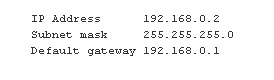
The connection to the Internet is shared to other computers on the local area network (LAN). The network adapter that is connected to the LAN is configured with a static IP address of 192.168.0.1 and a subnet mask of 255.255.255.0
On the client computer
To connect to the Internet by using the shared connection, you must confirm the LAN adapter IP configuration, and then configure the client computer. To confirm the LAN adapter IP configuration, follow these steps:
Log on to the client computer as Administrator or as Owner.
Click Start, and then click Control Panel.
Click Network and Internet Connections.
Click Network Connections.
Right-click Local Area Connection, and then click Properties.
Click the General tab, click Internet Protocol (TCP/IP) in the This connection uses the following items list, and then click Properties.
In the Internet Protocol (TCP/IP) Properties dialog box, click Obtain an IP address automatically (if it is not already selected), and then click OK. Note You can also assign a unique static IP address in the range of 192.168.0.2 to 192.168.0.254. For example, you can assign the following static IP address, subnet mask, and default gateway:
In the Local Area Connection Properties dialog box, click OK.
Quit Control Panel.
To configure the client computer to use the shared Internet connection, follow these steps:
Click Start, and then click Control Panel.
Click Network and Internet Connections.
Click Internet Options.
In the Internet Properties dialog box, click the Connections tab.
Click the Setup button. The New Connection Wizard starts.
On the Welcome to the New Connection Wizard page, click Next.
Click Connect to the Internet, and then click Next.
Click Set up my connection manually, and then click Next.
Click Connect using a broadband connection that is always on, and then clickNext.
On the Completing the New Connection Wizard page, click Finish.
Quit Control Panel.
When you now start Microsoft Internet Explorer, the client computer will try to connect to the Internet by using the host computer's shared Internet connection.
Troubleshooting
When you turn on Internet Connection Sharing on the host computer, the host computer's LAN adapter is automatically assigned the IP address of 192.168.0.1. Therefore, one of the following situations may occur:
IP address conflict Each computer on the LAN must have a unique IP address. If more than one computer has the same IP address, an IP conflict occurs, and one of the network adapters turns off until the conflict is resolved. To resolve this conflict, configure the client computer to automatically obtain an IP address, or assign it a unique IP address.
Loss of network connectivity If your network is configured with a different IP address range than Internet Connection Sharing uses, you will lose network connectivity with the host computer. To resolve this issue, configure the client computers to automatically obtain an IP address, or assign each client computer a unique IP address in the range of 192.168.0.2 to 192.168.0.254.
Mundu Radio is now available on Nokia and Java enable phones as well. Enjoy a number of internet radio stations right from your Nokia and Java enable mobiles.
Nokia and Java enable Device Software includes all the applications on your smartphone – email, organizer, media player, browser, calculator, mundu messenger and now the amazing mundu radio.
Mundu radio is feature-packed with rich UI and services like get lyrics, send lyrics, invite friends, managing playlist, dozens of pre-defined digital radio. In addition, if you have Wi-Fi or UMA enabled on your phone, enjoy the amazing Mundu radio without paying any data charges.
Mundu radio currently supports Nokia and Java enable phones.
We've got whats called Technology Convergance working for us. So when you feel that you've missed out on something, you can just pick up the closest device near you and truly Catch up. Reading newspapers while travelling to work is now a thing of the past! You can watch live television – news, entertainment, sports, or any of your favourite programmes on your mobile phone or desktop, whenever and wherever you are.
Nothing says it like A good Knock Knock
We dont like to harp on but come on, we have
* A rich, seamless, TV-like viewing experience. (Honey, i shrunk the TV!) * It's Plug and Play. Quick connectivity and less start-up time. * Have internet. Will play. Service available across all networks – low bandwidth GPRS, 3G, Wi-Fi and broadband Internet. * If you can type a text, you can use munduTV. The simplest navigation options that let you do Everything without reaching for a remote. * You can view this no matter what your phone number is. Network operator independent.
The team believes that there's a reason why our product is the future. And we've given you
* Option to Pause live TV. (Go make some popcorn.) * A personalized experience.(It's Your TV) * Channel browsing complete with channel logo, quality profile of the content being viewed. * Integrated Volume control with Quick mute option. (You're in charge) * Pay once. Single subscription for all your devices – handheld, desktop, laptop.
With many more features lined up, we quote Tolkien yet again, "So it begins." IF you want to download click here (first of all need registration)
Google Screensaver is a Windows screensaver that displays photos from different locations:
Your computer. You select a list of folders that contain photos and Google Screensaver monitors the JPEGs from these folders.
Picasa Web Albums. If you use Google's photo sharing site, you can view pictures from the most recently modified albums and from your contacts. It's probably the most interesting feature of Picasa Web Albums: you can monitor all the photos uploaded to your contacts' albums.
Web feeds. You can find them in photo sharing sites like Flickr, Picasa Web Albums or at this page. Some nice feeds: Flickr (Vista wallpapers, nature, architecture, landscape, Google food), Yahoo search (autumn, Dali, sunset) . To add a new source, right-click a link to a feed in IE and Firefox and select "Add to Google Photos Screensaver".
The screensaver acts like a slideshow so you can move to the next/previous photo using the mouse. The title and the author of a photo is always visible and you can go to the source of the photo by clicking to one of the links from the bottom of the window.
You can configure the visual effects (collage, wipe, pan and zoom, cross fade) and how often the photos change.
The screensaver is a part of Google Pack, but if you get it from this page you can install only the screensaver. Then you can uninstall Google Updater and keep the screensaver.
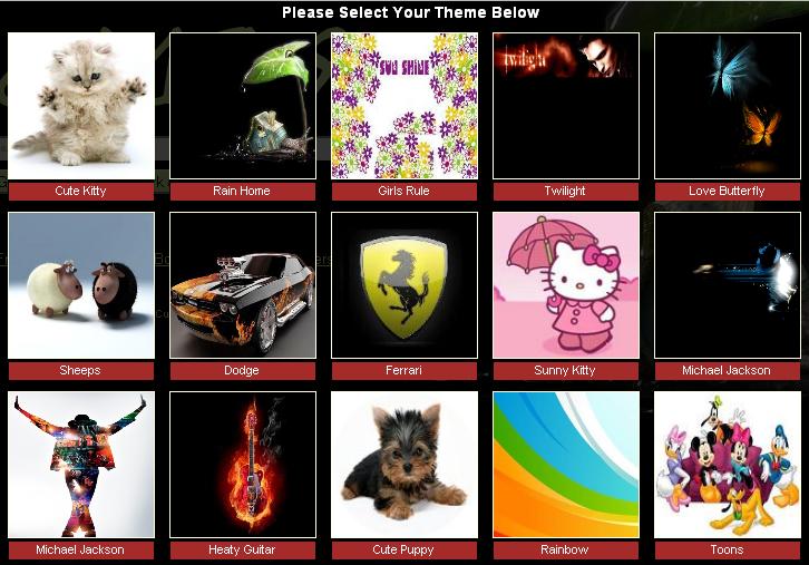
hello friends, Now you can make your own Search engine with your "Google custom search" with extraordinary theme. here some photo graph of search engine.
for more detailCLICK HERE .: Make your Personal Search Engine with your name :.
Instant Messaging digsby is a multiprotocol IM client that lets you chat with all your friends on AIM, MSN, Yahoo, ICQ, Google Talk, and Jabber with one simple to manage buddy list.
Email Notifications digsby is an email notification tool that alerts you of new email and lets you perform actions such as 'Delete' or 'Report Spam' with just one click. Social Networking digsby is a social networking tool that alerts you of events like new messages and gives you a live Newsfeed of what your friends are up to.
.: How to configure Yahoo account on your nokia phone (N73/N95/...) :.
here some information about Yahoo on your nokia phone without any software.
(IMP : You must enable POP3 access of yahoo mail account. Hint : Look inside ook inside Setting and POP forwarding Options on yahoo mail web site)
Open Messaging Application.
Goto Mail box. It asks you no mail defined. Define Now? choose "YES"
Mail setup wizard will start. press START to continue.
Mailbox Type choose POP3, Press next
On next screen type your Email address XXX@YAHOO.COM(IMP: press the Pencil key and highlight your email address then press copy. This will save you typing)
Press NEXT
Enter pop.mail.yahoo.fr as Incoming mail Server, Press NEXT
Enter smtp.mail.yahoo.fr as Outgoing mail server, Press NEXT
Acess Point, Choose Always ask or your preferred one , press NEXT
In mailbox name keep Yahoo, press NEXT
Click FINISH
Click Option and then setting
Choose E-mail
Press on Mailboxes and then on Yahoo
Press on connection setting
Press on Incoming E-mail
Enter Username as XXX@yahoo.com (You may press pencil and then paste)
In Password type your password
Scroll down to security port and choose SSL/TLS
Press back button
select Outgoing E-mail, Enter your username and password as described above
Scroll down to security port and choose SSL/TLS
Hitback button twice
Press on User setting
Enter your name as you want to display and then go back
Goto Retrival Settings
Click on E-mail to retrive and setting it to size limit and then enter 100 KB or whatever you like in next screen.Press Ok
Click on Back
If you have Unlimited GPRS connection then goto automatic retrieval and change it otherwise leave as it is.
Click back button multiple times so that you are back to main screen.
Now when you start Messaging Application you will see the Yahoo account goto it and retrieve your E-mail.
You can also send E-mail attach images,file and etc, Have fun
The Hypertext Transfer Protocol (HTTP) is an Application Layer protocol for distributed, collaborative, hypermedia information systems.[1]
HTTP is a request-response standard typical of client-server computing. In HTTP, web browsers or spiders typically act as clients, while an application running on the computer hosting the web site acts as a server. The client, which submits HTTP requests, is also referred to as the user agent. The responding server, which stores or creates resources such as HTML files and images, may be called the origin server. In between the user agent and origin server may be several intermediaries, such as proxies, gateways, and tunnels.
HTTP is not constrained in principle to using TCP/IP, although this is its most popular implementation platform. Indeed HTTP can be "implemented on top of any other protocol on the Internet, or on other networks." HTTP only presumes a reliable transport; any protocol that provides such guarantees can be used.[2]
Resources to be accessed by HTTP are identified using Uniform Resource Identifiers (URIs)—or, more specifically, Uniform Resource Locators (URLs)—using the http or https URI schemes.
Its use for retrieving inter-linked resources, called hypertext documents, led to the establishment of the World Wide Web in 1990 by English physicist Tim Berners-Lee.
The original version of HTTP, designated HTTP/1.0, was revised in HTTP/1.1. One of the characteristics in HTTP/1.0 was that it uses a separate connection to the same server for every document, while HTTP/1.1 can reuse the same connection to download, for instance, images for the just served page. Hence HTTP/1.1 may be faster as it takes time to set up such connections.
The standards development of HTTP has been coordinated by the World Wide Web Consortium and the Internet Engineering Task Force (IETF), culminating in the publication of a series of Requests for Comments (RFCs), most notably RFC 2616 (June 1999), which defines HTTP/1.1, the version of HTTP in common use.
Support for pre-standard HTTP/1.1 based on the then developing RFC 2068 was rapidly adopted by the major browser developers in early 1996. By March 1996, pre-standard HTTP/1.1 was supported in Netscape 2.0, Netscape Navigator Gold 2.01, Mosaic 2.7, Lynx 2.5, and in Internet Explorer 3.0. End user adoption of the new browsers was rapid. In March 1996, one web hosting company reported that over 40% of browsers in use on the Internet were HTTP 1.1 compliant. That same web hosting company reported that by June 1996, 65% of all browsers accessing their servers were HTTP/1.1 compliant.[3] The HTTP/1.1 standard as defined in RFC 2068 was officially released in January 1997. Improvements and updates to the HTTP/1.1 standard were released under RFC 2616 in June 1999.
An HTTP session is a sequence of network request-response transactions. An HTTP client initiates a request. It establishes a Transmission Control Protocol (TCP) connection to a particular port on a host (typically port 80; see List of TCP and UDP port numbers). An HTTP server listening on that port waits for a client's request message. Upon receiving the request, the server sends back a status line, such as "HTTP/1.1 200 OK", and a message of its own, the body of which is perhaps the requested resource, an error message, or some other information.
Request message
The request message consists of the following:
Request line, such as GET /images/logo.gif HTTP/1.1, which requests a resource called /images/logo.gif from server
Headers, such as Accept-Language: en
An empty line
An optional message body
The request line and headers must all end with (that is, a carriage return followed by a line feed). The empty line must consist of only and no other whitespace. In the HTTP/1.1 protocol, all headers except Host are optional.
A request line containing only the path name is accepted by servers to maintain compatibility with HTTP clients before the HTTP/1.0 specification in RFC1945.[4]
Request methods
An HTTP request made using telnet. The request, response headers and response body are highlighted.
HTTP defines eight methods (sometimes referred to as "verbs") indicating the desired action to be performed on the identified resource. What this resource represents, whether pre-existing data or data that is generated dynamically, depends on the implementation of the server. Often, the resource corresponds to a file or the output of an executable residing on the server.
HEAD
Asks for the response identical to the one that would correspond to a GET request, but without the response body. This is useful for retrieving meta-information written in response headers, without having to transport the entire content.
GET
Requests a representation of the specified resource. Note that GET should not be used for operations that cause side-effects, such as using it for taking actions in web applications. One reason for this is that GET may be used arbitrarily by robots or crawlers, which should not need to consider the side effects that a request should cause. See safe methods below.
POST
Submits data to be processed (e.g., from an HTML form) to the identified resource. The data is included in the body of the request. This may result in the creation of a new resource or the updates of existing resources or both.
PUT
Uploads a representation of the specified resource.
DELETE
Deletes the specified resource.
TRACE
Echoes back the received request, so that a client can see what intermediate servers are adding or changing in the request.
OPTIONS
Returns the HTTP methods that the server supports for specified URL. This can be used to check the functionality of a web server by requesting '*' instead of a specific resource.
CONNECT
Converts the request connection to a transparent TCP/IP tunnel, usually to facilitate SSL-encrypted communication (HTTPS) through an unencrypted HTTP proxy.[5]
PATCH
Is used to apply partial modifications to a resource.[6]
HTTP servers are required to implement at least the GET and HEAD methods[7] and, whenever possible, also the OPTIONS method.[citation needed]
Safe methods
Some methods (for example, HEAD, GET, OPTIONS and TRACE) are defined as safe, which means they are intended only for information retrieval and should not change the state of the server. In other words, they should not have side effects, beyond relatively harmless effects such as logging, caching, the serving of banner advertisements or incrementing a web counter. Making arbitrary GET requests without regard to the context of the application's state should therefore be considered safe.
By contrast, methods such as POST, PUT and DELETE are intended for actions which may cause side effects either on the server, or external side effects such as financial transactions or transmission of email. Such methods are therefore not usually used by conforming web robots or web crawlers, which tend to make requests without regard to context or consequences.
Despite the prescribed safety of GET requests, in practice their handling by the server is not technically limited in any way, and careless or deliberate programming can just as easily (or more easily, due to lack of user agent precautions) cause non-trivial changes on the server. This is discouraged, because it can cause problems for Web caching, search engines and other automated agents, which can make unintended changes on the server.
Idempotent methods and web applications
Methods PUT and DELETE are defined to be idempotent, meaning that multiple identical requests should have the same effect as a single request. Methods GET, HEAD, OPTIONS and TRACE, being prescribed as safe, should also be idempotent, as HTTP is a stateless protocol.
In contrast, the POST method is not necessarily idempotent, and therefore sending an identical POST request multiple times may further affect state or cause further side effects (such as financial transactions). In some cases this may be desirable, but in other cases this could be due to an accident, such as when a user does not realize that their action will result in sending another request, or they did not receive adequate feedback that their first request was successful. While web browsers may show alert dialog boxes to warn users in some cases where reloading a page may re-submit a POST request, it is generally up to the web application to handle cases where a POST request should not be submitted more than once.
Note that whether a method is idempotent is not enforced by the protocol or web server. It is perfectly possible to write a web application in which (for example) a database insert or other non-idempotent action is triggered by a GET or other request. Ignoring this recommendation, however, may result in undesirable consequences if a user agent assumes that repeating the same request is safe when it isn't.
Status codes
In HTTP/1.0 and since, the first line of the HTTP response is called the status line and includes a numeric status code (such as "404") and a textual reason phrase (such as "Not Found"). The way the user agent handles the response primarily depends on the code and secondarily on the response headers. Custom status codes can be used since, if the user agent encounters a code it does not recognize, it can use the first digit of the code to determine the general class of the response.[8]
Also, the standard reason phrases are only recommendations and can be replaced with "local equivalents" at the web developer's discretion. If the status code indicated a problem, the user agent might display the reason phrase to the user to provide further information about the nature of the problem. The standard also allows the user agent to attempt to interpret the reason phrase, though this might be unwise since the standard explicitly specifies that status codes are machine-readable and reason phrases are human-readable.
Persistent connections
In HTTP/0.9 and 1.0, the connection is closed after a single request/response pair. In HTTP/1.1 a keep-alive-mechanism was introduced, where a connection could be reused for more than one request.
Such persistent connections reduce lag perceptibly, because the client does not need to re-negotiate the TCP connection after the first request has been sent.
Version 1.1 of the protocol made bandwidth optimization improvements to HTTP/1.0. For example, HTTP/1.1 introduced chunked transfer encoding to allow content on persistent connections to be streamed, rather than buffered. HTTP pipelining further reduces lag time, allowing clients to send multiple requests before a previous response has been received to the first one. Another improvement to the protocol was byte serving, which is when a server transmits just the portion of a resource explicitly requested by a client.
HTTP session state
HTTP is a stateless protocol. The advantage of a stateless protocol is that hosts do not need to retain information about users between requests. For example, when a host needs to customize the content of a website for a user, the web application must be written to track the user's progress from page to page. A common method for solving this problem involves sending and receiving cookies. Other methods include server side sessions, hidden variables (when the current page is a form), and URL encoded parameters (such as /index.php?session_id=some_unique_session_code).
Secure HTTP
There are currently two methods of establishing a secure HTTP connection: the HTTPS URI scheme and the HTTP 1.1 Upgrade header, introduced by RFC 2817. Browser support for the Upgrade header is, however, nearly non-existent, hence the HTTPS URI scheme is still the dominant method of establishing a secure HTTP connection. Secure HTTP is notated by the prefix HTTPS:// instead of HTTP://
https URI scheme
https is a URI scheme that is, aside from the scheme token, syntactically identical to the http scheme used for normal HTTP connections, but which signals the browser to use an added encryption layer of SSL/TLS to protect the traffic. SSL is especially suited for HTTP since it can provide some protection even if only one side of the communication is authenticated. This is the case with HTTP transactions over the Internet, where typically only the server is authenticated (by the client examining the server's certificate).
HTTP 1.1 Upgrade header field
HTTP 1.1 introduced support for the Upgrade header field. In the exchange, the client begins by making a clear-text request, which is later upgraded to Transport Layer Security (TLS). Either the client or the server may request that the connection be upgraded. The most common usage is a clear-text request by the client followed by a server demand to upgrade the connection:
Client:
GET /encrypted-area HTTP/1.1
Host: www.example.com
The server returns a 426 status-code because 400 level codes indicate a client failure (see List of HTTP status codes), which correctly alerts legacy clients that the failure was client-related.
The benefits of using this method for establishing a secure connection are:
that it removes messy and problematic redirection and URL rewriting on the server side,
it allows virtual hosting of secured websites (although HTTPS also allows this using Server Name Indication), and
it reduces user confusion by providing a single way to access a particular resource.
A weakness with this method is that the requirement for a secure HTTP cannot be specified in the URI. In practice, the (untrusted) server will thus be responsible for enabling secure HTTP, not the (trusted) client.
Example session
Below is a sample conversation between an HTTP client and an HTTP server running on www.example.com, port 80.
Client request
 GET /index.html HTTP/1.1
Host: www.example.com
A client request is followed by a blank line, so that the request ends with a double newline, each in the form of a carriage return followed by a line feed. The "Host" header distinguishes between various DNS names sharing a single IP address, allowing name-based virtual hosting. While optional in HTTP/1.0, it is mandatory in HTTP/1.1.
Server response
 HTTP/1.1 200 OK
Date: Mon, 23 May 2005 22:38:34 GMT
Server: Apache/1.3.3.7 (Unix)  (Red-Hat/Linux)
Last-Modified: Wed, 08 Jan 2003 23:11:55 GMT
Etag: "3f80f-1b6-3e1cb03b"
Accept-Ranges: bytes
Content-Length: 438
Connection: close
Content-Type: text/html; charset=UTF-8
A server response is followed by a blank line and text of the requested page. The ETag (entity tag) header is used to determine if a cached version of the requested resource is identical to the current version of the resource on the server. Content-Type specifies the Internet media type of the data conveyed by the http message, while Content-Length indicates its length in bytes. The HTTP/1.1 webserver publishes its ability to respond to requests for certain byte ranges of the document by setting the header Accept-Ranges: bytes. This is useful if the client needs to have only certain portions[9] of a resource sent by the server, which is called byte serving. When Connection: close is sent in a header, it means that the web server will close the TCP connection immediately after the transfer of this package.
The Dynamic Host Configuration Protocol (DHCP) is a computer networking protocol used by hosts (DHCP clients) to retrieve IP address assignments and other configuration information.
DHCP uses a client-server architecture. The client sends a broadcast request for configuration information. The DHCP server receives the request and responds with configuration information from its configuration database.
In the absence of DHCP, all hosts on a network must be manually configured individually - a time-consuming and often error-prone undertaking.
RFC 1531 initially defined DHCP as a standard-track protocol in October 1993, succeeding the Bootstrap Protocol (BOOTP). The next update, RFC 2131 released in 1997 is the current DHCP definition for Internet Protocol version 4 (IPv4) networks. The extensions of DHCP for IPv6 (DHCPv6) were published as RFC 3315.
Technical overview
Dynamic Host Configuration Protocol automates network-parameter assignment to network devices from one or more fault-tolerant DHCP servers. Even in small networks, DHCP is useful because it can make it easy to add new machines to the network.
When a DHCP-configured client (a computer or any other network-aware device) connects to a network, the DHCP client sends a broadcast query requesting necessary information from a DHCP server. The DHCP server manages a pool of IP addresses and information about client configuration parameters such as default gateway, domain name, the DNS servers, other servers such as time servers, and so forth. On receiving a valid request, the server assigns the computer an IP address, a lease (length of time the allocation is valid), and other IP configuration parameters, such as the subnet mask and the default gateway. The query is typically initiated immediately after booting, and must complete before the client can initiate IP-based communication with other hosts.
Depending on implementation, the DHCP server may have three methods of allocating IP-addresses:
dynamic allocation: A network administrator assigns a range of IP addresses to DHCP, and each client computer on the LAN has its IP software configured to request an IP address from the DHCP server during network initialization. The request-and-grant process uses a lease concept with a controllable time period, allowing the DHCP server to reclaim (and then reallocate) IP addresses that are not renewed (dynamic re-use of IP addresses).
automatic allocation: The DHCP server permanently assigns a free IP address to a requesting client from the range defined by the administrator. This is like dynamic allocation, but the DHCP server keeps a table of past IP address assignments, so that it can preferentially assign to a client the same IP address that the client previously had.
static allocation: The DHCP server allocates an IP address based on a table with MAC address/IP address pairs, which are manually filled in (perhaps by a network administrator). Only requesting clients with a MAC address listed in this table will be allocated an IP address. This feature (which is not supported by all devices) is variously called Static DHCP Assignment (by DD-WRT), fixed-address (by the dhcpd documentation), DHCP reservation or Static DHCP (by Cisco/Linksys), and IP reservation or MAC/IP binding (by various other router manufacturers).
Technical details
DHCP uses the same two ports assigned by IANA for BOOTP: 67/udp for sending data to the server, and 68/udp for data to the client.
DHCP operations fall into four basic phases: IP discovery, IP lease offer, IP request, and IP lease acknowledgement.
Where a DHCP client and server are on the same subnet, they will communicate via UDP broadcasts. When the client and server are on different subnets, IP discovery and IP request messages are sent via UDP broadcasts, but IP lease offer and IP lease acknowledgement messages are sent via unicast.
DHCP discovery
The client broadcasts messages on the physical subnet to discover available DHCP servers. Network administrators can configure a local router to forward DHCP packets to a DHCP server from a different subnet. This client-implementation creates a User Datagram Protocol (UDP) packet with the broadcast destination of 255.255.255.255 or the specific subnet broadcast address.
A DHCP client can also request its last-known IP address (in the example below, 192.168.1.100). If the client remains connected to a network for which this IP is valid, the server might grant the request. Otherwise, it depends whether the server is set up as authoritative or not. An authoritative server will deny the request, making the client ask for a new IP immediately. A non-authoritative server simply ignores the request, leading to an implementation-dependent timeout for the client to give up on the request and ask for a new IP address.
DHCP offer
When a DHCP server receives an IP lease request from a client, it reserves an IP address for the client and extends an IP lease offer by sending a DHCPOFFER message to the client. This message contains the client's MAC address, the IP address that the server is offering, the subnet mask, the lease duration, and the IP address of the DHCP server making the offer.
The server determines the configuration based on the client's hardware address as specified in the CHADDR (Client Hardware Address) field. Here the server, 192.168.1.1, specifies the IP address in the YIADDR (Your IP Address) field.
DHCP request
A client can receive DHCP offers from multiple servers, but it will accept only one DHCP offer and broadcast a DHCP request message. Based on the Transaction ID field in the request, servers are informed whose offer the client has accepted. When other DHCP servers receive this message, they withdraw any offers that they might have made to the client and return the offered address to the pool of available addresses.
DHCP acknowledgement
When the DHCP server receives the DHCPREQUEST message from the client, the configuration processes enters its final phase. The acknowledgement phase involves sending a DHCPACK packet to the client. This packet includes the lease duration and any other configuration information that the client might have requested. At this point, the IP configuration process is completed.
The protocol expects the DHCP client to configure its network interface with the negotiated parameters.
DHCP option 6: DNS servers 9.7.10.15, 9.7.10.16, 9.7.10.18
After the client obtains an IP address, the client may use the Address Resolution Protocol (ARP) to prevent IP conflicts caused by overlapping address pools of DHCP servers.
DHCP information
A DHCP client may request more information than the server sent with the original DHCPOFFER. The client may also request repeat data for a particular application. For example, browsers use DHCP Inform to obtain web proxy settings via WPAD. Such queries do not cause the DHCP server to refresh the IP expiry time in its database.
DHCP releasing
The client sends a request to the DHCP server to release the DHCP information and the client deactivates its IP address. As client devices usually do not know when users may unplug them from the network, the protocol does not mandate the sending of DHCP Release.
Client configuration parameters
A DHCP server can provide optional configuration parameters to the client. RFC 2132 describes the available DHCP options defined by Internet Assigned Numbers Authority (IANA) - DHCP and BOOTP PARAMETERS.
A DHCP client can select, manipulate and overwrite parameters provided by a DHCP server.[1]
Options
An option exists to identify the vendor and functionality of a DHCP client. The information is a variable-length string of characters or octets which has a meaning specified by the vendor of the DHCP client. One method that a DHCP client can utilize to communicate to the server that it is using a certain type of hardware or firmware is to set a value in its DHCP requests called the Vendor Class Identifier (VCI) (Option 60). This method allows a DHCP server to differentiate between the two kinds of client machines and process the requests from the two types of modems appropriately. Some types of set-top boxes also set the VCI (Option 60) to inform the DHCP server about the hardware type and functionality of the device. The value that this option is set to give the DHCP server a hint about any required extra information that this client needs in a DHCP response.
DHCP Relaying
In small networks DHCP typically uses broadcasts. However, in some circumstances, unicast addresses will be used, for example: when networks have a single DHCP server that provides IP addresses for multiple subnets. When a router for such a subnet receives a DHCP broadcast, it converts it to unicast (with a destination MAC/IP address of the configured DHCP server, source MAC/IP of the router itself). The GIADDR field of this modified request is populated with the IP address of the router interface on which it received the original DHCP request. The DHCP server uses the GIADDR field to identify the subnet of the originating device in order to select an IP address from the correct pool. The DHCP server then sends the DHCP OFFER back to the router via unicast. The router then converts the DHCP OFFER back to a broadcast, sent out on the interface of the original device.
Security
This section contains close paraphrasing of one or more non-free copyrighted sources. Ideas in this article should be expressed in an original manner. See the talk page for details. (March 2009)
The basic DHCP protocol became a standard before network security became a significant issue: it includes no security features, and is potentially vulnerable to two types of attacks:[2]
Unauthorized DHCP Servers: as you cannot specify the server you want, an unauthorized server can respond to client requests, sending client network configuration values that are beneficial to the attacker. As an example, a hacker can hijack the DHCP process to configure clients to use a malicious DNS server or router (see also DNS cache poisoning).
Unauthorized DHCP Clients: By masquerading as a legitimate client, an unauthorized client can gain access to network configuration and an IP address on a network it should otherwise not be allowed to use. Also, by flooding the DHCP server with requests for IP addresses, it is possible for an attacker to exhaust the pool of available IP addresses, disrupting normal network activity (a denial of service attack).
To combat these threats RFC 3118 ("Authentication for DHCP Messages") introduced authentication information into DHCP messages, allowing clients and servers to reject information from invalid sources. Although support for this protocol is widespread, a large number of clients and servers still do not fully support authentication, thus forcing servers to support clients that do not support this feature. As a result, other security measures are usually implemented around the DHCP server (such as IPsec) to ensure that only authenticated clients and servers are granted access to the network.
Addresses should be dynamically linked to a secure DNS server, to allow troubleshooting by name rather than by a potentially unknown address.[citation needed] Effective DHCP-DNS linkage requires having a file of either MAC addresses or local names that will be sent to DNS that uniquely identifies physical hosts, IP addresses, and other parameters such as the default gateway, subnet mask, and IP addresses of DNS servers from a DHCP server. The DHCP server ensures that all IP addresses are unique, i.e., no IP address is assigned to a second client while the first client's assignment is valid (its lease has not expired). Thus IP address pool management is done by the server and not by a network administrator.
References
^ In Unix-like systems this client-level refinement typically takes place according to the values in a /etc/dhclient.conf configuration file.
The Transmission Control Protocol (TCP) is one of the core protocols of the Internet Protocol Suite. TCP is one of the two original components of the suite (the other being Internet Protocol, or IP), so the entire suite is commonly referred to as TCP/IP. Whereas IP handles lower-level transmissions from computer to computer as a message makes its way across the Internet, TCP operates at a higher level, concerned only with the two end systems, for example a Web browser and a Web server. In particular, TCP provides reliable, ordered delivery of a stream of bytes from a program on one computer to another program on another computer. Besides the Web, other common applications of TCP include e-mail and file transfer. Among its other management tasks, TCP controls segment size, flow control, the rate at which data is exchanged, and network traffic congestion.
In May, 1974, the Institute of Electrical and Electronic Engineers (IEEE) published a paper entitled "A Protocol for Packet Network Interconnection."[1] The paper's authors, Vint Cerf and Bob Kahn, described an internetworking protocol for sharing resources using packet-switching among the nodes. A central control component of this model was the Transmission Control Program that incorporated both connection-oriented links and datagram services between hosts. The monolithic Transmission Control Program was later divided into a modular architecture consisting of the Transmission Control Protocol at the connection-oriented layer and the Internet Protocol at the internetworking (datagram) layer. The model became known informally as TCP/IP, although formally it was henceforth called the Internet Protocol Suite.
Network function
TCP provides a communication service at an intermediate level between an application program and the Internet Protocol (IP). That is, when an application program desires to send a large chunk of data across the Internet using IP, instead of breaking the data into IP-sized pieces and issuing a series of IP requests, the software can issue a single request to TCP and let TCP handle the IP details.
IP works by exchanging pieces of information called packets. A packet is a sequence of bytes and consists of a header followed by a body. The header describes the packet's destination and, optionally, the routers to use for forwarding until it arrives at its final destination. The body contains the data which IP is transmitting.
Due to network congestion, traffic load balancing, or other unpredictable network behavior, IP packets can be lost, duplicated, or delivered out of order. TCP detects these problems, requests retransmission of lost packets, rearranges out-of-order packets, and even helps minimize network congestion to reduce the occurrence of the other problems. Once the TCP receiver has finally reassembled a perfect copy of the data originally transmitted, it passes that datagram to the application program. Thus, TCP abstracts the application's communication from the underlying networking details.
TCP is used extensively by many of the Internet's most popular applications, including the World Wide Web (WWW), E-mail, File Transfer Protocol, Secure Shell, peer-to-peer file sharing, and some streaming media applications.
TCP is optimized for accurate delivery rather than timely delivery, and therefore, TCP sometimes incurs relatively long delays (in the order of seconds) while waiting for out-of-order messages or retransmissions of lost messages. It is not particularly suitable for real-time applications such as Voice over IP. For such applications, protocols like the Real-time Transport Protocol (RTP) running over the User Datagram Protocol (UDP) are usually recommended instead.[2]
TCP is a reliable stream delivery service that guarantees delivery of a data stream sent from one host to another without duplication or losing data. Since packet transfer is not reliable, a technique known as positive acknowledgment with retransmission is used to guarantee reliability of packet transfers. This fundamental technique requires the receiver to respond with an acknowledgment message as it receives the data. The sender keeps a record of each packet it sends, and waits for acknowledgment before sending the next packet. The sender also keeps a timer from when the packet was sent, and retransmits a packet if the timer expires. The timer is needed in case a packet gets lost or corrupted.[2]
TCP consists of a set of rules: for the protocol, that are used with the Internet Protocol, and for the IP, to send data "in a form of message units" between computers over the Internet. At the same time that IP takes care of handling the actual delivery of the data, TCP takes care of keeping track of the individual units of data transmission, called segments, that a message is divided into for efficient routing through the network. For example, when an HTML file is sent from a Web server, the TCP software layer of that server divides the sequence of bytes of the file into segments and forwards them individually to the IP software layer (Internet Layer). The Internet Layer encapsulates each TCP segment into an IP packet by adding a header which includes (among other data) the destination IP address. Even though every packet has the same destination address, they can be routed on different paths through the network. When the client program on the destination computer receives them, the TCP layer (Transport Layer) reassembles the individual segments and ensures they are correctly ordered and error free as it streams them to an application.
TCP segment structure
A TCP segment consists of a segment header and a data section. The TCP header contains 10 mandatory fields, and an optional extension field (Options, pink background in table). The data section follows the header. Its contents are the payload data carried for the application.
TCP Header
Bit offset
0
1
2
3
4
5
6
7
8
9
10
11
12
13
14
15
16
17
18
19
20
21
22
23
24
25
26
27
28
29
30
31
0
Source port
Destination port
32
Sequence number
64
Acknowledgment number
96
Data offset
Reserved
C
W
R
E
C
E
U
R
G
A
C
K
P
S
H
R
S
T
S
Y
N
F
I
N
Window Size
128
Checksum
Urgent pointer
160 ...
Options (if Data Offset > 5)
...
Source port (16 bits) – identifies the sending port
Destination port (16 bits) – identifies the receiving port
Sequence number (32 bits) – has a dual role:
If the SYN flag is set, then this is the initial sequence number. The sequence number of the actual first data byte (and the acknowledged number in the corresponding ACK) will then be this sequence number plus 1.
If the SYN flag is clear, then this is the accumulated sequence number of the first data byte of this packet for the current session.
Acknowledgment number (32 bits) – if the ACK flag is set then the value of this field is the next sequence number that the receiver is expecting. This acknowledges receipt of all prior bytes (if any). The first ACK sent by each end acknowledges the other end's initial sequence number itself, but no data.
Data offset (4 bits) – specifies the size of the TCP header in 32-bit words. The minimum size header is 5 words and the maximum is 15 words thus giving the minimum size of 20 bytes and maximum of 60 bytes, allowing for up to 40 bytes of options in the header. This field gets its name from the fact that it is also the offset from the start of the TCP segment to the actual data.
Reserved (4 bits) – for future use and should be set to zero
CWR (1 bit) – Congestion Window Reduced (CWR) flag is set by the sending host to indicate that it received a TCP segment with the ECE flag set and had responded in congestion control mechanism (added to header by RFC 3168).
ECE (1 bit) – ECN-Echo indicates
If the SYN flag is set, that the TCP peer is ECN capable.
If the SYN flag is clear, that a packet with Congestion Experienced flag in IP header set is received during normal transmission(added to header by RFC 3168).
URG (1 bit) – indicates that the Urgent pointer field is significant
ACK (1 bit) – indicates that the Acknowledgment field is significant. All packets after the initial SYN packet sent by the client should have this flag set.
PSH (1 bit) – Push function. Asks to push the buffered data to the receiving application.
RST (1 bit) – Reset the connection
SYN (1 bit) – Synchronize sequence numbers. Only the first packet sent from each end should have this flag set. Some other flags change meaning based on this flag, and some are only valid for when it is set, and others when it is clear.
FIN (1 bit) – No more data from sender
Window (16 bits) – the size of the receive window, which specifies the number of bytes (beyond the sequence number in the acknowledgment field) that the receiver is currently willing to receive (see Flow control and Window Scaling)
Checksum (16 bits) – The 16-bit checksum field is used for error-checking of the header and data
Urgent pointer (16 bits) – if the URG flag is set, then this 16-bit field is an offset from the sequence number indicating the last urgent data byte
Options (Variable 0-320 bits, divisible by 32) – The length of this field is determined by the data offset field. Options 0 and 1 are a single byte (8 bits) in length. The remaining options indicate the total length of the option (expressed in bytes) in the second byte.[3] Some options may only be sent when SYN is set; they are indicated below as [SYN].
0 (8 bits) - End of options list
1 (8 bits) - No operation (NOP, Padding) This may be used to align option fields on 32-bit boundaries for better performance.
2,4,SS (32 bits) - Maximum segment size (see maximum segment size) [SYN]
3,3,S (24 bits) - Window scale (see window scaling for details) [SYN][4]
4,2 (16 bits) - Selective Acknowledgement permitted. [SYN] (See selective acknowledgments for details)[5]
5,N,BBBB,EEEE,... (variable bits, N is either 10, 18, 26, or 34)- Selective ACKnowlegement (SACK)[6] These first two bytes are followed by a list of 1-4 blocks being selectively acknowledged, specified as 32-bit begin/end pointers.
8,10,TTTT,EEEE (80 bits)- Timestamp and echo of previous timestamp (see TCP Timestamps for details)[7]
(The remaining options are obsolete, experimental, not yet standardized, or unassigned)
Protocol operation
A Simplified TCP State Diagram. See TCP EFSM diagram for a more detailed state diagram including the states inside the ESTABLISHED state.
TCP protocol operations may be divided into three phases. Connections must be properly established in a multi-step handshake process (connection establishment) before entering the data transfer phase. After data transmission is completed, the connection termination closes established virtual circuits and releases all allocated resources.
A TCP connection is managed by an operating system through a programming interface that represents the local end-point for communications, the Internet socket. During the lifetime of a TCP connection it undergoes a series of state changes:
LISTEN : In case of a server, waiting for a connection request from any remote client.
SYN-SENT : waiting for the remote peer to send back a TCP segment with the SYN and ACK flags set. (usually set by TCP clients)
SYN-RECEIVED : waiting for the remote peer to send back an acknowledgment after having sent back a connection acknowledgment to the remote peer. (usually set by TCP servers)
ESTABLISHED : the port is ready to receive/send data from/to the remote peer.
FIN-WAIT-1
FIN-WAIT-2
CLOSE-WAIT
CLOSING
LAST-ACK
TIME-WAIT : represents waiting for enough time to pass to be sure the remote peer received the acknowledgment of its connection termination request. According to RFC 793 a connection can stay in TIME-WAIT for a maximum of four minutes.
CLOSED
Connection establishment
To establish a connection, TCP uses a three-way handshake. Before a client attempts to connect with a server, the server must first bind to a port to open it up for connections: this is called a passive open. Once the passive open is established, a client may initiate an active open. To establish a connection, the three-way (or 3-step) handshake occurs:
The active open is performed by the client sending a SYN to the server. It sets the segment's sequence number to a random value A.
In response, the server replies with a SYN-ACK. The acknowledgment number is set to one more than the received sequence number (A + 1), and the sequence number that the server chooses for the packet is another random number, B.
Finally, the client sends an ACK back to the server. The sequence number is set to the received acknowledgement value i.e. A + 1, and the acknowledgement number is set to one more than the received sequence number i.e. B + 1.
At this point, both the client and server have received an acknowledgment of the connection.
Data transfer
There are a few key features that set TCP apart from User Datagram Protocol:
Ordered data transfer - the destination host rearranges according to sequence number[2]
Retransmission of lost packets - any cumulative stream not acknowledged will be retransmitted[2]
Discarding duplicate packets
Error-free data transfer
Flow control - limits the rate a sender transfers data to guarantee reliable delivery. The receiver continually hints the sender on how much data can be received (controlled by the sliding window). When the receiving host's buffer fills, the next acknowledgment contains a 0 in the window size, to stop transfer and allow the data in the buffer to be processed.[2]
Congestion control [2]
Reliable transmission
TCP uses a sequence number to identify each byte of data. The sequence number identifies the order of the bytes sent from each computer so that the data can be reconstructed in order, regardless of any fragmentation, disordering, or packet loss that may occur during transmission. For every payload byte transmitted the sequence number must be incremented. In the first two steps of the 3-way handshake, both computers exchange an initial sequence number (ISN). This number can be arbitrary, and should in fact be unpredictable, in order to avoid a TCP Sequence Prediction Attack.
TCP primarily uses a cumulative acknowledgment scheme, where the receiver sends an acknowledgment signifying that the receiver has received all data preceding the acknowledged sequence number. Essentially, the first byte in a segment's data field is assigned a sequence number, which is inserted in the sequence number field, and the receiver sends an acknowledgment specifying the sequence number of the next byte they expect to receive. For example, if computer A sends 4 bytes with a sequence number of 100 (conceptually, the four bytes would have a sequence number of 100, 101, 102, & 103 assigned) then the receiver would send back an acknowledgment of 104 since that is the next byte it expects to receive in the next packet.
In addition to cumulative acknowledgments, TCP receivers can also send selective acknowledgments to provide further information (see selective acknowledgments).
If the sender infers that data has been lost in the network, it retransmits the data.
Error detection
Sequence numbers and acknowledgments cover discarding duplicate packets, retransmission of lost packets, and ordered-data transfer. To assure correctness a checksum field is included (see TCP segment structure for details on checksumming).
The TCP checksum is a weak check by modern standards. Data Link Layers with high bit error rates may require additional link error correction/detection capabilities. The weak checksum is partially compensated for by the common use of a CRC or better integrity check at layer 2, below both TCP and IP, such as is used in PPP or the Ethernet frame. However, this does not mean that the 16-bit TCP checksum is redundant: remarkably, introduction of errors in packets between CRC-protected hops is common, but the end-to-end 16-bit TCP checksum catches most of these simple errors [9]. This is the end-to-end principle at work.
Flow control
TCP uses an end-to-end flow control protocol to avoid having the sender send data too fast for the TCP receiver to receive and process it reliably. Having a mechanism for flow control is essential in an environment where machines of diverse network speeds communicate. For example, if a PC sends data to a hand-held PDA that is slowly processing received data, the PDA must regulate data flow so as not to be overwhelmed.[2]
TCP uses a sliding window flow control protocol. In each TCP segment, the receiver specifies in the receive window field the amount of additional received data (in bytes) that it is willing to buffer for the connection. The sending host can send only up to that amount of data before it must wait for an acknowledgment and window update from the receiving host.
TCP sequence numbers and receive windows behave very much like a clock. The receive window shifts each time the receiver receives and acknowledges a new segment of data. Once it runs out of sequence numbers, the sequence number loops back to 0.
When a receiver advertises a window size of 0, the sender stops sending data and starts the persist timer. The persist timer is used to protect TCP from a deadlock situation that could arise if the window size update from the receiver is lost and the sender has no more data to send while the receiver is waiting for the new window size update. When the persist timer expires, the TCP sender sends a small packet so that the receiver sends an acknowledgement with the new window size.
If a receiver is processing incoming data in small increments, it may repeatedly advertise a small receive window. This is referred to as the silly window syndrome, since it is inefficient to send only a few bytes of data in a TCP segment, given the relatively large overhead of the TCP header. TCP senders and receivers typically employ flow control logic to specifically avoid repeatedly sending small segments. The sender-side silly window syndrome avoidance logic is referred to as Nagle's algorithm.
Congestion control
The final main aspect of TCP is congestion control. TCP uses a number of mechanisms to achieve high performance and avoid 'congestion collapse', where network performance can fall by several orders of magnitude. These mechanisms control the rate of data entering the network, keeping the data flow below a rate that would trigger collapse.
Acknowledgments for data sent, or lack of acknowledgments, are used by senders to infer network conditions between the TCP sender and receiver. Coupled with timers, TCP senders and receivers can alter the behavior of the flow of data. This is more generally referred to as congestion control and/or network congestion avoidance.
Modern implementations of TCP contain four intertwined algorithms: Slow-start, congestion avoidance, fast retransmit, and fast recovery (RFC 2581).
In addition, senders employ a retransmission timeout (RTO) that is based on the estimated round-trip time (or RTT) between the sender and receiver, as well as the variance in this round trip time. The behavior of this timer is specified in RFC 2988. There are subtleties in the estimation of RTT. For example, senders must be careful when calculating RTT samples for retransmitted packets; typically they use Karn's Algorithm or TCP timestamps (see RFC 1323). These individual RTT samples are then averaged over time to create a Smoothed Round Trip Time (SRTT) using Jacobson's algorithm. This SRTT value is what is finally used as the round-trip time estimate.
Enhancing TCP to reliably handle loss, minimize errors, manage congestion and go fast in very high-speed environments are ongoing areas of research and standards development. As a result, there are a number of TCP congestion avoidance algorithm variations.
Maximum segment size
The Maximum segment size (MSS) is the largest amount of data, specified in bytes, that TCP is willing to send in a single segment. For best performance, the MSS should be set small enough to avoid IP fragmentation, which can lead to excessive retransmissions if there is packet loss. To try to accomplish this, typically the MSS is negotiated using the MSS option when the TCP connection is established, in which case it is determined by the maximum transmission unit (MTU) size of the data link layer of the networks to which the sender and receiver are directly attached. Furthermore, TCP senders can use Path MTU discovery to infer the minimum MTU along the network path between the sender and receiver, and use this to dynamically adjust the MSS in order to avoid IP fragmentation within the network.
no need to read
Window scaling
Main article: TCP window scale option
For more efficient use of high bandwidth networks, a larger TCP window size may be used. The TCP window size field controls the flow of data and its value is limited to between 2 and 65,535 bytes.
Since the size field cannot be expanded, a scaling factor is used. The TCP window scale option, as defined in RFC 1323, is an option used to increase the maximum window size from 65,535 bytes to 1 Gigabyte. Scaling up to larger window sizes is a part of what is necessary for TCP Tuning.
The window scale option is used only during the TCP 3-way handshake. The window scale value represents the number of bits to left-shift the 16-bit window size field. The window scale value can be set from 0 (no shift) to 14 for each direction independently. Both sides must send the option in their SYN segments to enable window scaling in either direction.
Some routers and packet firewalls rewrite the window scaling factor during a transmission. This causes sending and receiving sides to assume different TCP window sizes. The result is non-stable traffic that may be very slow. The problem is visible on some sending and receiving sites which are behind the path of defective routers.[10]
TCP Timestamps
TCP timestamps, defined in RFC 1323, help TCP compute the round-trip time between the sender and receiver. Timestamp options include a 4-byte timestamp value, where the sender inserts its current value of its timestamp clock, and a 4-byte echo reply timestamp value, where the receiver generally inserts the most recent timestamp value that it has received. The sender uses the echo reply timestamp in an acknowledgment to compute the total elapsed time since the acknowledged segment was sent.[2]
TCP timestamps are also used to help in the case where TCP sequence numbers encounter their 232 bound and "wrap around" the sequence number space. This scheme is known as Protect Against Wrapped Sequence numbers, or PAWS (see RFC 1323 for details). Furthermore, the Eifel detection algorithm, defined in RFC 3522, which detects unnecessary loss recovery requires TCP timestamps.
Out of band data
One is able to interrupt or abort the queued stream instead of waiting for the stream to finish. This is done by specifying the data as urgent. This will tell the receiving program to process it immediately, along with the rest of the urgent data. When finished, TCP informs the application and resumes back to the stream queue. An example is when TCP is used for a remote login session, the user can send a keyboard sequence that interrupts or aborts the program at the other end. These signals are most often needed when a program on the remote machine fails to operate correctly. The signals must be sent without waiting for the program to finish its current transfer.[2]
TCP OOB data was not designed for the modern Internet. The urgent pointer only alters the processing on the remote host and doesn't expedite any processing on the network itself. When it gets to the remote host there are two slightly different interpretations of the protocol which means only single bytes of OOB data are reliable. This is assuming it's reliable at all as it's one of the least commonly used protocol elements and tends to be poorly implemented. [11][12]
Forcing data delivery
Normally, TCP waits for the buffer to exceed the maximum segment size before sending any data. This creates serious delays when the two sides of the connection are exchanging short messages and need to receive the response before continuing. For example, the login sequence at the beginning of a telnet session begins with the short message "Login", and the session cannot make any progress until these five characters have been transmitted and the response has been received. This process can be seriously delayed by TCP's normal behavior when the message is provided to TCP in several send calls.
However, an application can force delivery of segments to the output stream using a push operation provided by TCP to the application layer.[2] This operation also causes TCP to set the PSH flag or control bit to ensure that data will be delivered immediately to the application layer by the receiving transport layer.
In the most extreme cases, for example when a user expects each keystroke to be echoed by the receiving application, the push operation can be used each time a keystroke occurs. More generally, application programs use this function to force output to be sent after writing a character or line of characters. By forcing the data to be sent immediately, delays and wait time are reduced.
Connection termination
The connection termination phase uses, at most, a four-way handshake, with each side of the connection terminating independently. When an endpoint wishes to stop its half of the connection, it transmits a FIN packet, which the other end acknowledges with an ACK. Therefore, a typical tear-down requires a pair of FIN and ACK segments from each TCP endpoint.
A connection can be "half-open", in which case one side has terminated its end, but the other has not. The side that has terminated can no longer send any data into or receive any data from the connection, but the other side can (but generally if it tries, this should result in no acknowledgment and therefore a timeout, or else result in a positive RST, and either way thereby the destruction of the half-open socket).
It is also possible to terminate the connection by a 3-way handshake, when host A sends a FIN and host B replies with a FIN & ACK (merely combines 2 steps into one) and host A replies with an ACK.[13] This is perhaps the most common method.
It is possible for both hosts to send FINs simultaneously then both just have to ACK. This could possibly be considered a 2-way handshake since the FIN/ACK sequence is done in parallel for both directions.
Some host TCP stacks may implement a "half-duplex" close sequence, as Linux or HP-UX do. If such a host actively closes a connection but still has not read all the incoming data the stack already received from the link, this host will send a RST instead of a FIN (Section 4.2.2.13 in RFC 1122). This allows a TCP application to be sure that the remote application has read all the data the former sent - waiting the FIN from the remote side when it will actively close the connection. However, the remote TCP stack cannot distinguish between a Connection Aborting RST and this Data Loss RST - both will cause the remote stack to throw away all the data it received, but the application still didn't read.[clarification needed]
Some application protocols may violate the OSI model layers, using the TCP open/close handshaking for the application protocol open/close handshaking - these may find the RST problem on active close. As an example:
s = connect(remote);

send(s, data);

close(s);
For a usual program flow like above, a TCP/IP stack like that described above does not guarantee that all the data will arrive to the other application unless the programmer is sure that the remote side will not send anything.
Vulnerabilities
Denial of service
By using a spoofed IP address and repeatedly sending purposely assembled SYN packets, attackers can cause the server to consume large amounts of resources keeping track of the bogus connections. This is known as a SYN flood attack. Proposed solutions to this problem include SYN cookies and Cryptographic puzzles. Sockstress is a similar attack, against which no defense is yet known.[citation needed] An advanced DoS attack involving the exploitation of the TCP Persist Timer was analyzed at Phrack #66.[14]
Connection hijacking
Main article: TCP sequence prediction attack
An attacker who is able to eavesdrop a TCP session and redirect packets can hijack a TCP connection. To do so, the attacker learns the sequence number from the ongoing communication and forges a false segment that looks like the next segment in the stream. Such a simple hijack can result in one packet being erroneously accepted at one end. When the receiving host acknowledges the extra segment to the other side of the connection, synchronization is lost. Hijacking might be combined with ARP or routing attacks that allow taking control of the packet flow, so as to get permanent control of the hijacked TCP connection.[15]
Impersonating a different IP address was possible prior to RFC 1948, when the initial sequence number was easily guessable. That allowed an attacker to blindly send a sequence of packets that the receiver would believe to come from a different IP address, without the need to deploy ARP or routing attacks: it is enough to ensure that the legitimate host of the impersonated IP address is down, or bring it to that condition using denial of service attacks. This is why the initial sequence number is chosen at random.
TCP ports
Main article: TCP and UDP port
TCP uses the notion of port numbers to identify sending and receiving application end-points on a host, or Internet sockets. Each side of a TCP connection has an associated 16-bit unsigned port number (0-65535) reserved by the sending or receiving application. Arriving TCP data packets are identified as belonging to a specific TCP connection by its sockets, that is, the combination of source host address, source port, destination host address, and destination port. This means that a server computer can provide several clients with several services simultaneously, as long as a client takes care of initiating any simultaneous connections to one destination port from different source ports.
Port numbers are categorized into three basic categories: well-known, registered, and dynamic/private. The well-known ports are assigned by the Internet Assigned Numbers Authority (IANA) and are typically used by system-level or root processes. Well-known applications running as servers and passively listening for connections typically use these ports. Some examples include: FTP (21), SSH (22), TELNET (23), SMTP (25) and HTTP (80). Registered ports are typically used by end user applications as ephemeral source ports when contacting servers, but they can also identify named services that have been registered by a third party. Dynamic/private ports can also be used by end user applications, but are less commonly so. Dynamic/private ports do not contain any meaning outside of any particular TCP connection.
Development
TCP is a complex protocol. However, while significant enhancements have been made and proposed over the years, its most basic operation has not changed significantly since its first specification RFC 675 in 1974, and the v4 specification RFC 793, published in September 1981. RFC 1122, Host Requirements for Internet Hosts, clarified a number of TCP protocol implementation requirements. RFC 2581, TCP Congestion Control, one of the most important TCP-related RFCs in recent years, describes updated algorithms to be used in order to avoid undue congestion. In 2001, RFC 3168 was written to describe explicit congestion notification (ECN), a congestion avoidance signalling mechanism.
The original TCP congestion avoidance algorithm was known as "TCP Tahoe", but many alternative algorithms have since been proposed (including TCP Reno, TCP Vegas, FAST TCP, TCP New Reno, and TCP Hybla).
TCP Interactive (iTCP) [16] is a research effort into TCP extensions that allows applications to subscribe to TCP events and register handler components that can launch applications for various purposes, including application assisted congestion control.
TCP over wireless networks
TCP has been optimized for wired networks. Any packet loss is considered to be the result of congestion and the congestion window size is reduced dramatically as a precaution. However, wireless links are known to experience sporadic and usually temporary losses due to fading, shadowing, hand off, and other radio effects, that cannot be considered congestion. After the (erroneous) back-off of the congestion window size, due to wireless packet loss, there can be a congestion avoidance phase with a conservative decrease in window size. This causes the radio link to be underutilized. Extensive research has been done on the subject of how to combat these harmful effects. Suggested solutions can be categorized as end-to-end solutions (which require modifications at the client and/or server), link layer solutions (such as RLP in CDMA2000), or proxy based solutions (which require some changes in the network without modifying end nodes).
Hardware implementations
One way to overcome the processing power requirements of TCP is to build hardware implementations of it, widely known as TCP Offload Engines (TOE). The main problem of TOEs is that they are hard to integrate into computing systems, requiring extensive changes in the operating system of the computer or device. One company to develop such a device was Alacritech.
Debugging
A packet sniffer, which intercepts TCP traffic on a network link, can be useful in debugging networks, network stacks and applications which use TCP by showing the user what packets are passing through a link. Some networking stacks support the SO_DEBUG socket option, which can be enabled on the socket using setsockopt. That option dumps all the packets, TCP states and events on that socket which will be helpful in debugging. netstat is another utility that can be used for debugging.
Alternatives
For many applications TCP is not appropriate. One big problem (at least with normal implementations) is that the application cannot get at the packets coming after a lost packet until the retransmitted copy of the lost packet is received. This causes problems for real-time applications such as streaming multimedia (such as Internet radio), real-time multiplayer games and voice over IP (VoIP) where it is sometimes more useful to get most of the data in a timely fashion than it is to get all of the data in order.
For both historical and performance reasons, most storage area networks (SANs) prefer to use Fibre Channel protocol (FCP) instead of TCP/IP.
Also for embedded systems, network booting and servers that serve simple requests from huge numbers of clients (e.g. DNS servers) the complexity of TCP can be a problem. Finally some tricks such as transmitting data between two hosts that are both behind NAT (using STUN or similar systems) are far simpler without a relatively complex protocol like TCP in the way.
Generally where TCP is unsuitable the User Datagram Protocol (UDP) is used. This provides the application multiplexing and checksums that TCP does, but does not handle building streams or retransmission giving the application developer the ability to code those in a way suitable for the situation and/or to replace them with other methods like forward error correction or interpolation.
SCTP is another IP protocol that provides reliable stream oriented services not so dissimilar from TCP. It is newer and considerably more complex than TCP, and has not yet seen widespread deployment. However, it is especially designed to be used in situations where reliability and near-real-time considerations are important.
Venturi Transport Protocol (VTP) is a patented proprietary protocol that is designed to replace TCP transparently in order to overcome perceived inefficiencies related to wireless data transport.
TCP also has some issues in high bandwidth utilization environments. The TCP congestion avoidance algorithm works very well for ad-hoc environments where it is not known who will be sending data, but if the environment is predictable, a timing based protocol such as Asynchronous Transfer Mode (ATM) can avoid the overhead of the retransmits that TCP needs.
Multipurpose Transaction Protocol (MTP/IP) is patented proprietary software that is designed to adaptively achieve high throughput and transaction performance in a wide variety of network conditions, particularly those where TCP is perceived to be inefficient.
Checksum computation
TCP checksum for IPv4
When TCP runs over IPv4, the method used to compute the checksum is defined in RFC 793:
The checksum field is the 16 bit one's complement of the one's complement sum of all 16-bit words in the header and text. If a segment contains an odd number of header and text octets to be checksummed, the last octet is padded on the right with zeros to form a 16-bit word for checksum purposes. The pad is not transmitted as part of the segment. While computing the checksum, the checksum field itself is replaced with zeros.
In other words, after appropriate padding, all 16-bit words are added using one's complement arithmetic. The sum is then bitwise complemented and inserted as the checksum field. A pseudo-header that mimics the IPv4 packet header used in the checksum computation is shown in the table below.
TCP pseudo-header (IPv4)
Bit offset
0–3
4–7
8–15
16–31
0
Source address
32
Destination address
64
Zeros
Protocol
TCP length
96
Source port
Destination port
128
Sequence number
160
Acknowledgement number
192
Data offset
Reserved
Flags
Window
224
Checksum
Urgent pointer
256
Options (optional)
256/288+
Data
The source and destination addresses are those of the IPv4 header. The protocol value is 6 for TCP (cf. List of IP protocol numbers). The TCP length field is the length of the TCP header and data.
TCP checksum for IPv6
When TCP runs over IPv6, the method used to compute the checksum is changed, as per RFC 2460:
Any transport or other upper-layer protocol that includes the addresses from the IP header in its checksum computation must be modified for use over IPv6, to include the 128-bit IPv6 addresses instead of 32-bit IPv4 addresses.
A pseudo-header that mimics the IPv6 header for computation of the checksum is shown below.
TCP pseudo-header (IPv6)
Bit offset
0 - 7
8–15
16–23
24–31
0
Source address
32
64
96
128
Destination address
160
192
224
256
TCP length
288
Zeros
Next header
320
Source port
Destination port
352
Sequence number
384
Acknowledgement number
416
Data offset
Reserved
Flags
Window
448
Checksum
Urgent pointer
480
Options (optional)
480/512+
Data
Source address – the one in the IPv6 header
Destination address – the final destination; if the IPv6 packet doesn't contain a Routing header, that will be the destination address in the IPv6 header, otherwise, at the originating node, it will be the address in the last element of the Routing header, and, at the receiving node, it will be the destination address in the IPv6 header.
TCP length – the length of the TCP header and data;
Next Header – the protocol value for TCP
Checksum offload
Many TCP/IP software stack implementations provide options to use hardware assistance to automatically compute the checksum in the network adapter prior to transmission onto the network or upon reception from the network for validation.
References
^ Vinton G. Cerf, Robert E. Kahn, A Protocol for Packet Network Intercommunication, IEEE Transactions on Communications, Vol. 22, No. 5, May 1974 pp. 637-648
^ abcdefghijComer, Douglas E. (2006). Internetworking with TCP/IP:Principles, Protocols, and Architecture. 1 (5th ed.). Prentice Hall. ISBN 0130905526.
^http://www.iana.org/assignments/tcp-parameters/
^RFC 1323, TCP Extensions for High Performance, Section 2.2